3D Shoe Sole Design: Outsole, Midsole and Heel Modeling Guide
3D Shoe Sole Design: A Complete Guide to Outsole, Midsole and Heel Modeling
The sole is the structural spine of any shoe. It determines silhouette, weight distribution, flex behavior, and factory cost. Yet the SERP for "3d shoe sole design" returns mostly academic papers and forum threads, with nothing a working designer can actually follow. This guide fills that gap: a practitioner workflow covering outsole NURBS surfacing, midsole lattice and gyroid generation, heel stacking geometry, top piece placement, and how to prep every component for either injection mold tooling or direct 3D printing.
3D footwear design career overview
Key Takeaways
- The outsole, midsole, heel, and top piece are four separate CAD objects, each with its own geometry requirements and mold constraints.
- NURBS-based tools (Rhino, iCad3D+) give you continuous-curvature surfaces that translate cleanly to injection tooling.
- A 2025 NIH peer-reviewed study found that gyroid TPU midsoles at variable infill densities reduced peak knee adduction moments by up to 10.5% vs. traditional wedge insoles (PMC12864507, 2025).
- For 3D printing molds, lattice interiors cut material use by 40% without sacrificing stiffness (Forward AM / BASF whitepaper, 2022).
- iCad3D+ (Icad Universe) handles outsole, heel, top piece and plateau as independent components, making iteration fast at the concept stage.
What Are the Parts of a Shoe Sole?
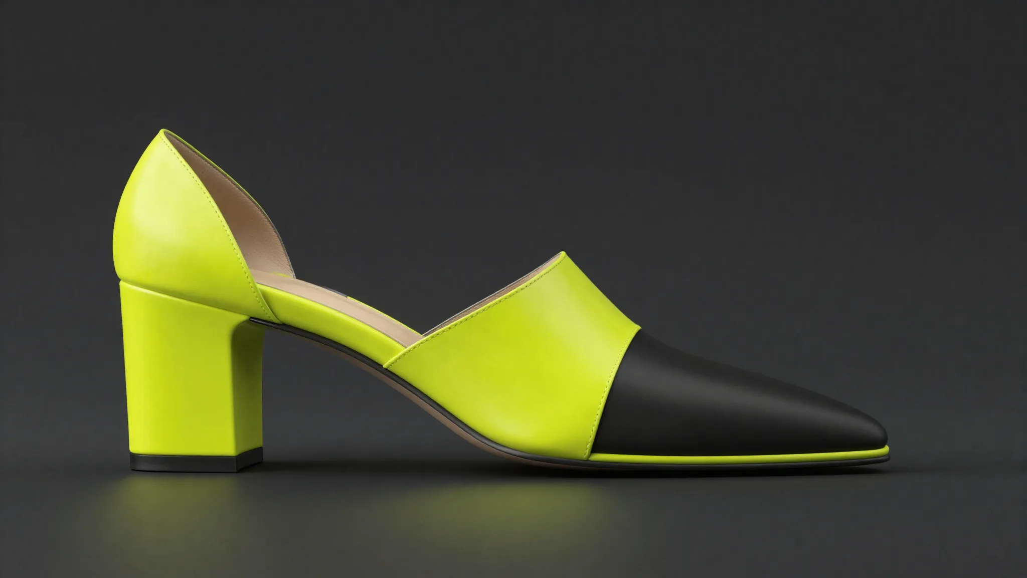
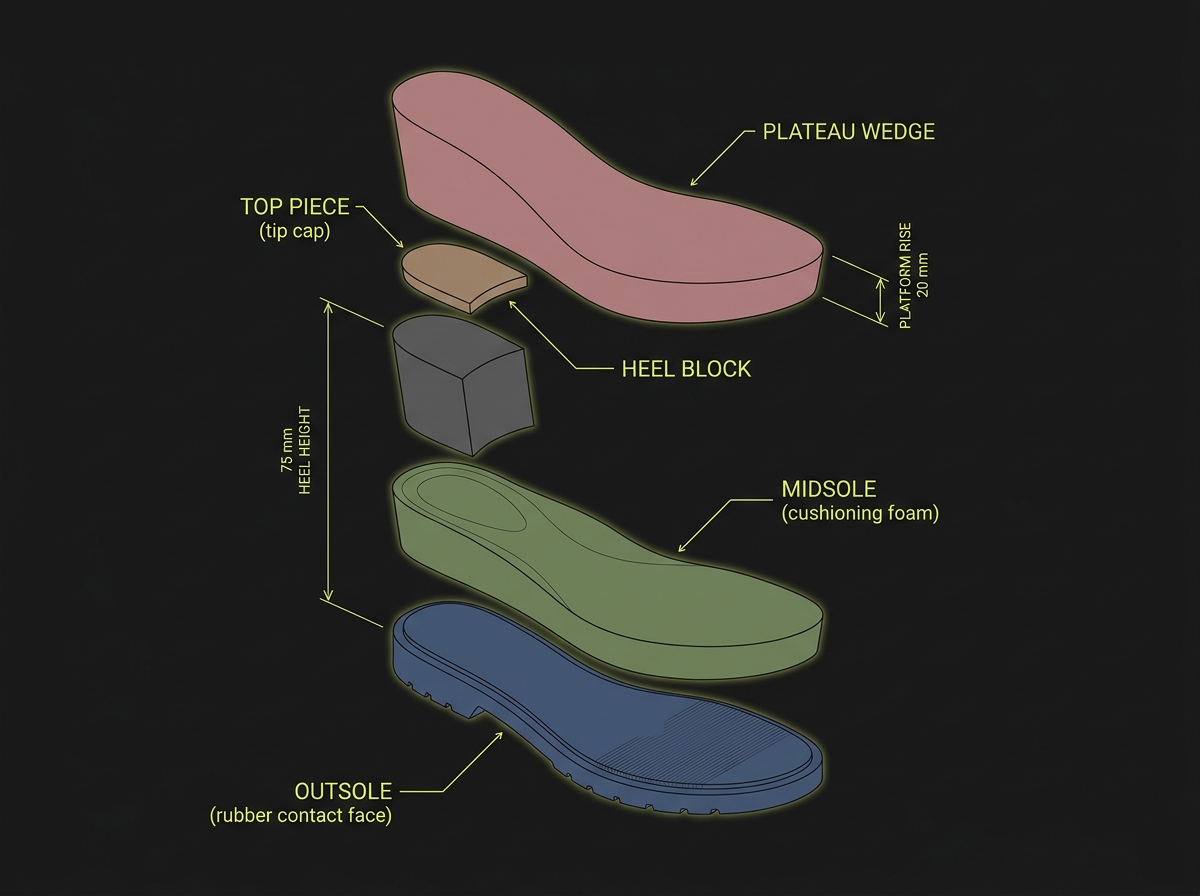
Before opening any CAD tool, you need the correct vocabulary. Sole anatomy is the foundation of every workflow decision downstream. The four primary components are: outsole (the rubber or leather contact face), midsole (the cushioning layer between outsole and upper), heel (the rear elevation block), and top piece (the small sacrificial cap at the heel's tip). A fifth element, the plateau or platform, appears on wedge and platform styles as a forefoot elevation that balances heel height.
In professional CAD practice, each of these is a separate object. They share positional relationships but carry their own material assignments, mold requirements, and tolerance stacks. Treating them as one mesh is the fastest path to rework.
Do You Need Rhino or a Specialized Footwear CAD Tool?
The honest answer depends on what you're designing and where the geometry ends up. Rhino with Grasshopper is the industry default for freeform NURBS outsole work, and it's the right choice when you need tight interoperability with industrial tooling partners who expect .3dm or IGES files. Its NetworkSrf and Sweep2 commands handle complex outsole curvature well. Lofted heel sidewalls, filleted edges between heel and outsole, and parting-line drafts are all manageable once you know the workflow.
That said, Rhino has no footwear-specific intelligence. You build every construction aid from scratch: last alignment geometry, camber curves, featherline profiles. For designers who work primarily in concept development or across many SKUs per season, that overhead adds up quickly.
iCad3D+ (developed by Icad Universe, formerly Crispin) is built specifically for the footwear pipeline. It manages outsole, heel, top piece and plateau as parameterized components inside a dedicated panel, all pre-registered to the last geometry. The construction steps I describe below reflect the iCad3D+ workflow, but I'll mark where Rhino diverges so you can map across.
Full software comparison including Rhino, iCad3D+, and CLO
How to Model a 3D Outsole: NURBS Surface Workflow
NURBS outsole modeling requires three things before you touch a surface command: a clean last mesh or NURBS shell, a confirmed featherline (the perimeter edge where upper meets sole), and a clear spec for outsole thickness at toe, waist, and heel. Without those three inputs, every surface you build is provisional.
Step 1 — Extract the Featherline and Ground Plane
In iCad3D+, open the Components panel from the lower toolbar. Select "Create Component," then "Create surface with profile" to extract the sole base directly from the last's bottom. The software projects the last's contact geometry onto a construction plane, giving you the featherline as a closed curve.
In Rhino, you accomplish this manually: project the last mesh silhouette onto a ground plane CPlane, then rebuild the resulting curve with a controlled point count before using it as the rail for your outsole sweeps.
Step 2 — Build the Outsole Body
With the featherline in place, add cross-section profiles at regular intervals along the length. In iCad3D+, the Curves panel lets you define lateral profiles with independent offset values, so the outsole tapers toward the toe without manual trimming. Assign a distinct color in the materials panel immediately — it helps enormously when the assembly grows.
In Rhino, use NetworkSrf across three or more section curves and the featherline rail. Check for zebra striping across the heel-to-waist junction: any kink there telegraphs directly into the mold parting line and causes flash issues in production.
Step 3 — Tread Geometry and Flex Zones
Tread depth and flex-zone placement are not purely aesthetic choices. They are stiffness-tuning inputs. A continuous groove running perpendicular to the metatarsal break line drops bending resistance at exactly the right anatomical point. A solid heel pad without relief grooves transmits impact force upward unattenuated.
For Rhino, tread grooves are Boolean subtractions from the outsole body. Keep groove depth at 2-3 mm for standard rubber compounds and maintain a 1.5-degree draft angle on groove sidewalls for clean demolding. The flex zone at the forefoot typically lives between 35% and 45% of total shoe length, measured from the heel seat.
In iCad3D+, grooves and surface reliefs are added as separate profile curves on the outsole component. You can copy curve styles across profiles to maintain consistent tread width along the length.
How to Model a 3D Midsole: From EVA Block to Lattice Structure
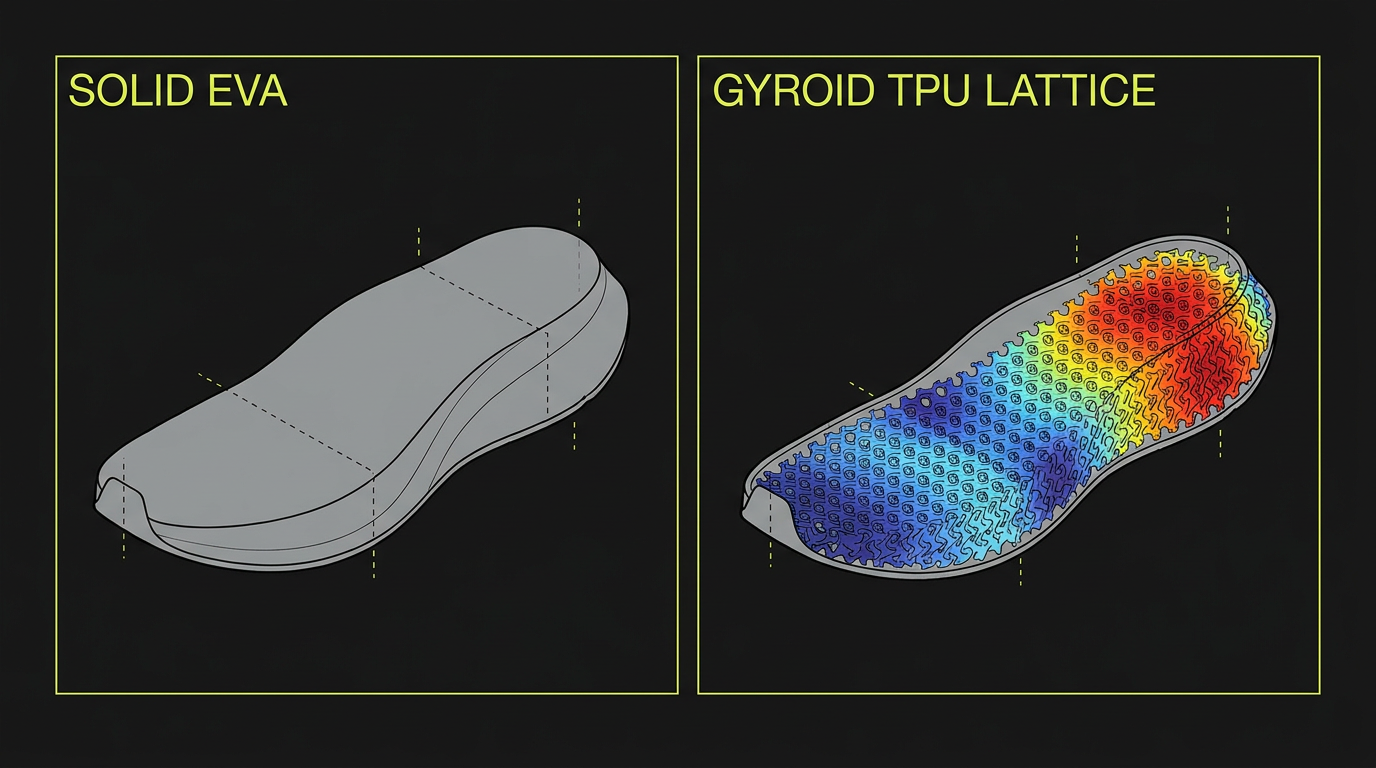
Midsole design sits at the intersection of aesthetics, biomechanics, and manufacturing method. A conventional EVA midsole is a single extruded or compression-molded block. A 3D-printed midsole can be a variable-density lattice where each zone has a different stiffness. The modeling approach differs entirely between these two paths.
Conventional EVA Midsole in CAD
Model the midsole as a trimmed solid between the outsole top face and the last's strobel (bottom) surface. In iCad3D+, the midsole is an additional component in the same panel as the outsole. In Rhino, you'll use the outsole's upper surface and a projected strobel curve as your boundary inputs for a Loft or NetworkSrf.
Key geometry checks before export: verify the midsole has consistent 7-10 mm thickness at waist (for most athletic silhouettes), that the forefoot tapers appropriately to 4-5 mm at the toe spring, and that the heel seat is coplanar with the outsole top face within 0.1 mm tolerance.
Lattice and Gyroid Midsole Modeling for 3D Printing
This is where the gap in the current SERP is most visible. Existing results either cite commercial case studies or academic papers, but don't bridge them to the actual Grasshopper or nTopology workflow a designer would use.
The adidas 4DFWD midsole is the most cited example: its lattice reduces peak braking force during running by an average of 15% and generates three times as much forward motion under vertical loading compared to previous 4D generations. That lattice was selected from five million possible structures (adidas official press release, news.adidas.com, May 2021). Carbon's Digital Light Synthesis process tested more than 50 lattice designs and 150 material formulations for the Futurecraft 4D, achieving near-zero support material waste (Carbon3D adidas case study, carbon3d.com).
For independent designers, the practical workflow runs through Grasshopper (Rhino's parametric environment):
- Define the midsole boundary as a closed NURBS polysurface in Rhino.
- In Grasshopper, use a component like Intralattice or a custom gyroid function to populate the interior volume with a periodic minimal surface.
- Set infill density as a variable driven by a gradient map: denser (stiffer) at the lateral heel, lighter (softer) at the medial arch.
This variable-density approach has direct clinical backing. A 2025 peer-reviewed study (n=21) published on PMC found that 3D-printed TPU midsoles with gyroid infill at 30% lateral / 5% medial density reduced the first peak knee adduction moment by 10.5% (P=0.001) and the second peak by 8.6% (P=0.032), outperforming traditional 5-degree lateral wedge insoles, which achieved only 7.9% reduction in the first peak (PMC12864507, National Institutes of Health, 2025).
New Balance's TripleCell heel lattice, printed in Formlabs Rebound Resin via stereolithography, is 10% lighter than the conventional 990v5 while maintaining equivalent cushioning, with New Balance holding exclusive footwear rights to the resin (Formlabs New Balance blog, formlabs.com).
How to Model a 3D Heel: Stacking and Top Piece Geometry
Heel modeling involves two separate objects: the heel body (the visible elevation block) and the top piece (the small rubber or nylon cap that contacts the ground at the heel tip). Confusing these in the CAD file costs time and money downstream. The top piece must be modeled as a separate component because it uses a different material, replaces independently during wear, and has its own mold or press-cut tooling.
In iCad3D+, the heel and top piece are distinct entries in the Components panel. The guided creation workflow lets you set heel height, block taper, and top piece thickness as numeric inputs with live preview. The "Recalculate preview" button updates the viewport before you commit, which saves a lot of undo cycles at the concept stage.
Heel Stacking in Four CAD Steps
- Set heel height from the ground plane to the heel seat (the surface that contacts the last's heel cup). Confirm this dimension against the last's pitch spec.
- Define the heel block's silhouette curves in four views simultaneously: front, side, top, and perspective. Use the side view for profile decisions, the front view for waist width, and the top view for plan-shape.
- Position the heel so its top face is co-planar with the outsole's heel seat surface. In iCad3D+, use the alignment commands in the positioning panel, then confirm with the green checkmark. In Rhino, align using the Orient3Pt command referencing three points on the last heel cup surface.
- Model the top piece as a 4-6 mm thick solid at the heel's base, slightly inset from the heel block perimeter to create a shadow gap detail if the design calls for it. Set 1.5-2 degree draft on the top piece sidewalls for mold release.
Upper modeling workflow that pairs with this sole guide
Preparing Sole Geometry for Mold-Making or 3D Printing
The final CAD step before handoff differs depending on whether you're going to injection tooling or direct 3D printing. Getting this wrong means either a failed mold quote or a print that cracks on its first flex test.
Mold-Prep for Injection or Compression Molding
Check every vertical or near-vertical surface for draft angle: a minimum of 1 degree, with 2-3 degrees preferred on textured surfaces. Identify the parting line early: for outsoles it typically runs along the featherline perimeter, but complex tread patterns may require a stepped or contoured parting line that adds mold cost.
Farsoon's 3D-printed metal molds illustrate how far mold technology has moved. As of August 2024, their printed molds had been used to produce over 100 million pairs of shoes, with their EVA conformal-cooling mold claiming a 100% boost in production efficiency. Their popcorn mold features 16,000 ventilation holes each 0.1 mm in diameter at 95% surface density (3D Printing Industry, August 2024).
For resin-printed molds (suitable for small-run production), Forward AM and BASF reduced polyurethane footwear mold production time from 8 weeks to a few days using Ultracur3D RG 1100 B resin. An internal lattice structure cut material use by 40% versus solid molds, while maintaining required stiffness and temperature resistance (Forward AM use-case whitepaper).
Geometry Prep for Direct FFF or SLS Printing
For direct printing (prototypes or production-intent TPU soles), ensure the outsole body is a single closed watertight solid with no internal geometry. Remove any NURBS surface overlaps before export. Target a minimum wall thickness of 1.2 mm for SLS TPU and 1.5 mm for FFF. Export at 0.01 mm chord deviation to capture tread detail without producing a file over 200 MB.
FAQ
What is the difference between outsole, midsole, and insole in 3D shoe design?
The outsole is the external ground-contact layer, typically rubber or leather. The midsole sits between outsole and upper and handles cushioning, often EVA or 3D-printed TPU lattice. The insole (or footbed) is the removable upper layer inside the shoe. In CAD, each is modeled as a separate closed solid with its own material and thickness spec.
Can I model a 3D-printed lattice midsole without Grasshopper?
Yes, though with more manual effort. nTopology and Materialise Magics both offer lattice generation without parametric scripting. Some slicer software (like Bambu Studio or Chitubox) can apply infill patterns, but these give you less geometric control than a proper Grasshopper or nTopology workflow. For variable-density zones tied to biomechanical targets, a parametric tool is the more reliable path.
How do I set the correct draft angle for a shoe sole mold?
A minimum of 1 degree is needed for smooth surfaces; 2-3 degrees for textured or grained surfaces. The draft direction must align with the mold's opening direction. Measure draft angle in a dedicated analysis tool (Rhino's DraftAngleAnalysis command, or any CAM system's draft check) before sending geometry to the mold maker. Errors found by the toolmaker cost significantly more to fix than errors caught in CAD.
What file formats do footwear mold makers typically accept?
Most toolmakers prefer STEP (.stp) or IGES (.igs) for NURBS geometry, and STL or OBJ for mesh-based or 3D-printed components. iCad3D+ exports to these formats directly from the Components panel. If you're working in Rhino, export STEP with solids and surfaces combined in one file. Always confirm the required format with your specific mold partner before finalizing the CAD model.
Is iCad3D+ suitable for complex sculptural soles?
iCad3D+ handles most commercial sole geometries well, including stilettos, stacked heels, wedges, and platforms. For highly sculptural soles with organic freeform surfaces (think architectural fashion footwear), a hybrid approach works: rough out the shape in iCad3D+ using the free-profile modeling mode, then refine in Rhino for surface quality. The import/export workflow between the two tools is clean via IGES or OBJ.
Learn the Full Workflow with Susanna Zampieri
This guide covers the core CAD logic behind sole component modeling. Applying it fluently across real shoe projects, working to commercial tolerances, and presenting finished 3D models to luxury clients takes structured practice on real-world briefs.
Susanna Zampieri is an official iCad3D+ trainer with 10+ years in the footwear industry, working across 50+ luxury brands and training 100+ designers. Her course covers the complete design pipeline from last analysis and upper construction through sole modeling, material presentation, and project delivery. More about her background and method at /en/susanna-zampieri.