How to Model a Shoe Upper in 3D: The Professional Last-Based Workflow
How to Model a Shoe Upper in 3D: The Professional Last-Based Workflow
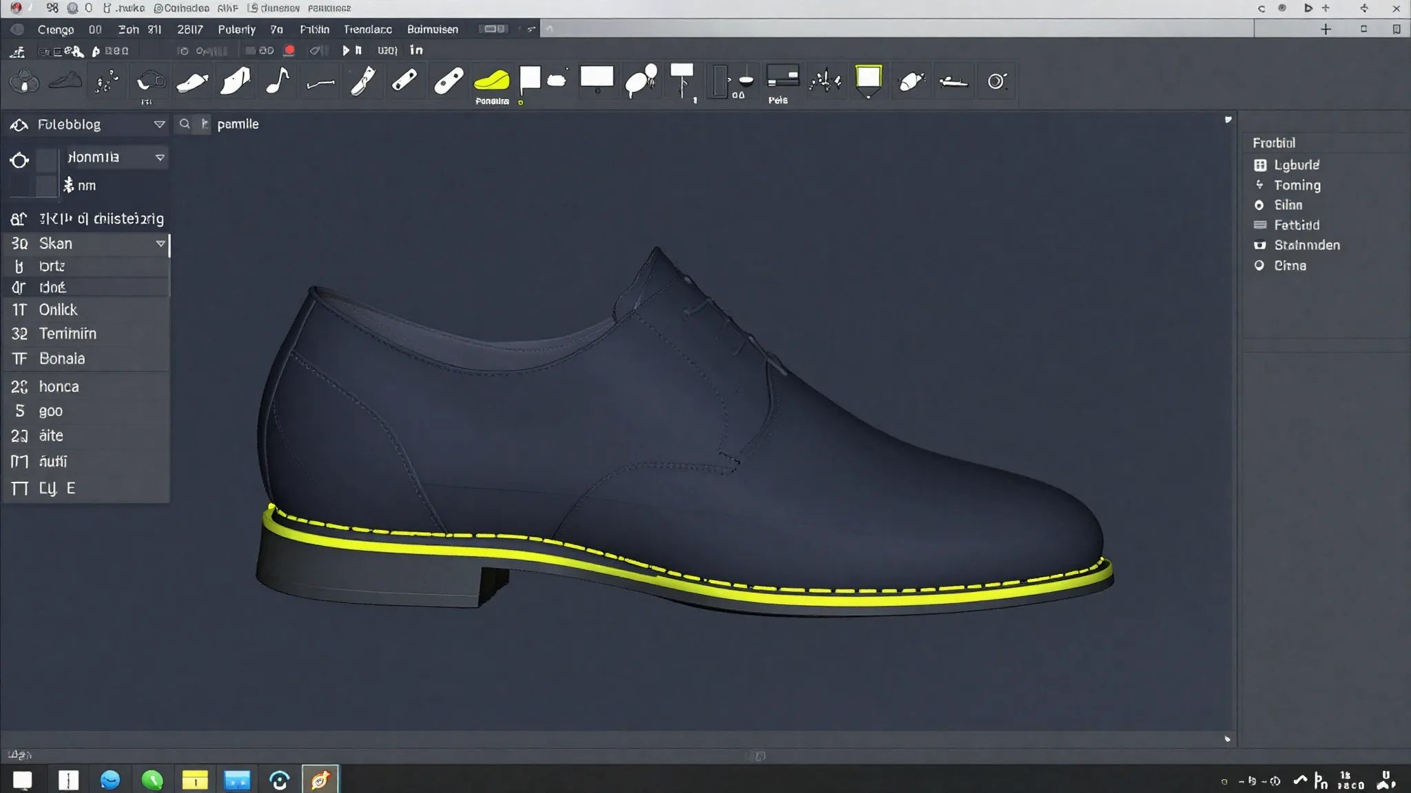
Every Blender tutorial on shoe upper modeling starts the same way: subdivide a cube, wrap it around a last-shaped reference, sculpt until it looks like a shoe. The result is convincing on screen. But if you hand that mesh to a pattern maker or a lasting technician, you will hear the same answer: we cannot use this.
The problem is not the software. It is the workflow. A shoe upper built for production must start from the last surface, not from a polygon mesh. It needs construction lines that define manufacturable panels, material thickness built in as an offset, and a path to a flat 2D pattern that feeds directly into a clicking press or CNC cutter. That is what we cover here.
This article walks you through the professional last-based workflow, step by step, using iCad3D+ as the reference environment. If you are evaluating software options first, the comparison of footwear CAD tools is a useful starting point before reading further.
comparison of footwear CAD tools
Key Takeaways
- The shoe last is the mandatory construction substrate for a production-valid upper, not optional reference geometry.
- Style lines and construction lines drawn on the last surface define real, sewable panels.
- Material thickness must be modeled as an offset surface, not added later.
- Accurate 3D-to-2D flattening directly determines material efficiency: optimized nesting reaches 73.89% utilization for Oxford uppers (Heliyon/PMC, 2024).
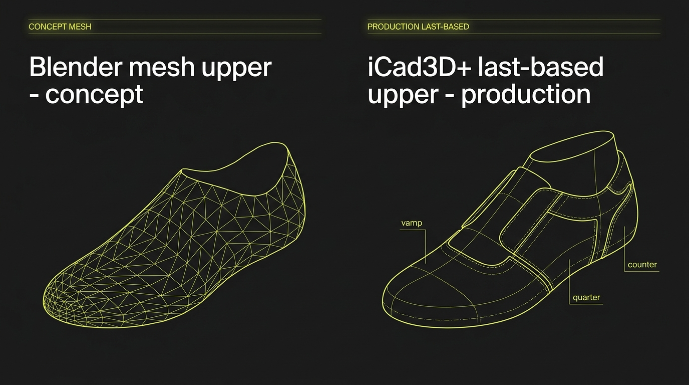
- Blender and Maya are appropriate for concept visualization; they do not produce a flattening pipeline or construction-line logic for cut-and-sew production.
Why Does the Workflow Tool You Choose Matter This Much?
The footwear industry divides 3D design software into two fundamentally different categories. According to The Interline's DPC Report 2026, CAD tools (Rhinoceros, SolidWorks, iCad3D+) focus on accuracy, tolerances, and production output. Polygonal/mesh tools (Blender, Cinema4D, Maya) focus on visual quality, animation, and digital presentation. Only CAD tools produce geometry suitable for mold-making, lasting, or pattern flattening.
[CITATION CAPSULE: The footwear 3D software landscape divides sharply between CAD tools oriented toward accuracy and production (Rhinoceros, SolidWorks, iCad3D+) and polygonal/mesh tools built for visual output (Blender, Maya). Only CAD tools produce geometry a pattern maker or lasting technician can actually use. (The Interline, DPC Report 2026)]
This distinction matters because the cost of physical prototyping is real and measurable. Preliminary industry research from DUO Design Studio, reported by The Interline (January 2025), estimates that an average shoe design requires 13 physical samples before sign-off, with roughly 26 million samples produced across the fashion footwear industry each year. Digital workflows built on accurate 3D geometry reduce that number. The same source suggests that digital sampling can cut sample production and shipping costs by over 60%, though the methodology is still being validated with Colorado State University and should be treated as directional.
If your 3D model cannot flatten to a usable pattern, it cannot replace a physical sample. That is the core argument for learning the professional workflow.
What Is a Shoe Last and Why Is It Not Optional?
The last is the 3D form around which every upper is built. It defines foot volume, the flex point, the pitch, and the lasting allowance at the bottom edge. In a professional workflow, every surface you draw for the upper lives on, or offset from, that last surface. It is not background reference geometry. It is the construction substrate.
In over ten years of 3D footwear design and training 100+ students from luxury brands, the most common mistake I see from designers coming from Blender or general CAD is treating the last as a visual guide. They build their upper shapes in space and then try to fit them to the last afterward. The result is always the same: panels that look right in the viewport but distort badly when you try to flatten them, because the curvature relationships were never grounded in the last surface geometry.
The professional starting point is the opposite: prepare the last correctly, and every surface you build on top of it inherits the curvature data that makes flattening possible. iCad3D+, developed by INESCOP (the Spanish footwear technology research center), is built specifically around this principle. It has over 2,000 installations in 39 countries (INESCOP official site) and is the only footwear CAD platform that integrates 3D upper design and 2D pattern engineering in one simultaneous working environment.
Step 1: Prepare and Flatten the Last
Before you draw a single line on the upper, the last must be correctly prepared for flattening (what iCad3D+ calls "spianamento"). This phase involves applying a mesh to the last surface, defining the center line and the fit axis, and verifying that the geometry accurately reflects the real physical last.
Mesh quality here is non-negotiable. Uneven coverage produces distortions that propagate into every panel you create later. iCad3D+ provides visual feedback: the mesh turns blue where it exceeds the surface boundary, red where it overlaps. You correct those zones before moving forward.
Once the preparation is complete, the software generates the "developed surface" (or camicia in Italian-language documentation), which is the flat representation of the last surface. This is your working canvas for the entire upper. Think of it as unrolling a curved 3D shape into a flat plane with known distortion characteristics. Everything you draw in this flat view projects accurately back onto the 3D last.
Step 2: Define Style Lines and Construction Lines
This is where shoe design actually happens. Style lines define the visual silhouette of the upper: where the vamp ends, where the quarter begins, how the counter sits. Construction lines define the manufacturing logic: the top line, the lasting margin at the bottom, the overlap between panels for stitching.
Many designers conflate style lines and construction lines, treating them as the same thing. They are not. A style line defines what the shoe looks like. A construction line defines how it is built. The throat line of a Derby shoe is a style line. The 10 mm lasting allowance running along the bottom edge is a construction line. Both need to be present in the 3D model for the pattern to be production-ready.
In iCad3D+, you draw directly on the developed flat surface (which is the most precise option for geometric lines and specific measurements), or directly on the 3D last surface (which is better for lines that follow foot curvature, like the top line or the vamp curve). Most experienced designers use both views during the same session.
The drawing tools available cover every production use case:
| Tool | Best for |
|---|---|
| Freehand curve | Organic lines, vamp curve, top-line profile |
| B-spline | Controlled curves with editable control points |
| Parallel offset | Seam allowances, lasting margins at constant distance |
| Perpendicular | Precise angles at panel junctions |
| Standard shapes | Geometric details, logo placement zones |
The lines you draw here become the boundaries of your panels. Precision at this stage directly determines pattern accuracy downstream.
Step 3: Manage Seam Allowances and Symmetry
Once the main style and construction lines are in place, you add seam allowances and mirror the geometry across the last's center line.
Seam Allowances as Dependent Offsets
Seam allowances in a professional CAD workflow are not separate lines drawn by hand. They are dependent parallel offsets of the original line. When you move the original style line, the seam allowance follows automatically. This is critical for an upper with 8 to 12 panels: you cannot afford to manually re-draw allowances every time a designer requests a 2 mm adjustment to the vamp line.
In iCad3D+, each allowance is named, saved, and reusable across models or colorways. You can also create variable-width allowances where the offset distance changes along the line's path. This handles the classic case where an allowance needs to be wider at a corner or junction point.
Symmetry Axes
For symmetric uppers, iCad3D+ lets you define additional symmetry axes beyond the default center line. Once an axis is active, every line you draw is simultaneously mirrored. This halves the drawing time for standard lace-up shoes, and makes it straightforward to build left/right-specific variants with minimal extra work.
Step 4: Create the 2D Panels
With your lines complete, you generate the actual 2D panels (pieces) that will become your cutting patterns. Each panel is defined by a closed perimeter formed by the lines you have already drawn.
The workflow is direct: activate the panel creation tool, click the lines that form the boundary in sequence (getting as close as possible to intersection points), and confirm. A dialog appears to assign properties: name, group membership, offset value, material thickness, and edge profile.
Organizing panels into groups by material type matters enormously on complex uppers. You might have one group for the main leather panels, one for the textile lining, and one for stiffeners. You set offset and thickness values at the group level once, and every panel in that group inherits those values. This is the kind of workflow efficiency that adds up across a 20-style collection.
In training sessions with professional students from luxury brands, we consistently find that designers who skip the grouping step during initial modeling spend 40-60% more time on revisions when material specifications change late in development. Group-based offset management is one of the highest-leverage habits in professional upper modeling.
Advanced panel options worth knowing:
- Insides: internal elements (decorative stitching, perforations, embroidered logos) that do not define the panel boundary but are managed within the panel object.
- Intersection edit: corrects errors in boundary selection without redrawing lines.
- Duplicate panel: creates a variant from an existing panel geometry without starting from scratch.
Step 5: Apply Material Thickness and Project to 3D
This step is where the model goes from flat pattern engineering back to full 3D visualization, with the material stack properly represented.
For each panel or panel group, you set three values before generating the 3D projection:
- Offset: the distance from the last surface, simulating the physical stack of lining, foam, and main material beneath the outer layer.
- Thickness: the extrusion height of the panel (the visible panel depth when looking at an edge-on cross-section).
- Edge profile: the shape of the panel edge (square, beveled, rounded), which affects how panels sit against each other and how stitching looks.
iCad3D+ includes a dropper tool to copy offset/thickness values from one panel and paste them onto another. On an upper with many panels of the same leather type, this cuts setup time considerably.
Why does this accuracy matter for production? A peer-reviewed study in Heliyon (May 2024) quantified upper material utilization at 73.89% for Oxford-style footwear through optimized 2D pattern nesting. The mathematical model in that study predicted material consumption with an adjusted R-squared of 0.9546. In plain terms: accurate 3D-to-2D flattening is directly tied to how efficiently you use expensive leather. A 3mm error in a panel shape at the 3D stage becomes material waste at the cutting stage.
[CITATION CAPSULE: Optimized 2D pattern nesting for Oxford shoe uppers achieves 73.89% average material utilization. A predictive model achieved adjusted R-squared of 0.9546 and Pearson r = 0.9847, demonstrating that 3D-to-2D flattening accuracy directly controls material efficiency at the cutting stage. (Heliyon, Elsevier, peer-reviewed, May 2024)]
Once thickness values are set, the panels project onto the 3D last surface. You verify positioning, panel alignment, and visual appearance before moving on to stitching, material mapping, and colorway variants.
Step 6: Stitching, Materials, and Colorways
With the upper panels built and projected in 3D, the finishing layer adds production detail and presentation quality.
Stitching is applied directly to panel edges, with control over stitch type and spacing. This is not decorative: the stitch pattern in the 3D model corresponds to the actual sewing instructions and feeds into technical file outputs.
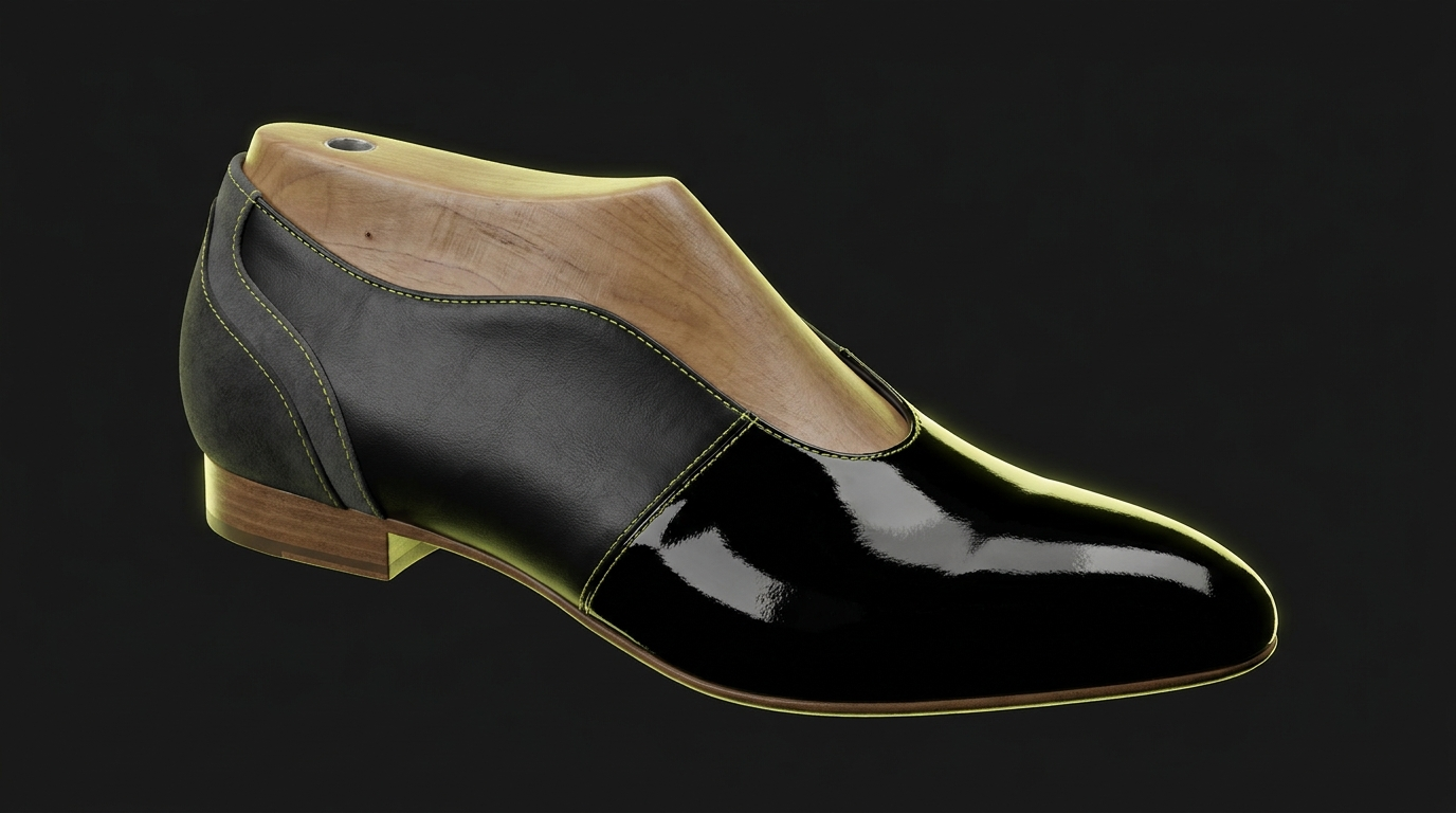
Material mapping applies real textile or leather textures to the 3D surface, giving a realistic visualization of how different material choices read on the final shoe. This is useful for client presentations and colorway approvals without physical samples.
Colorways let you generate multiple color options from the same model structure. Changing a colorway does not require redrawing the upper. This is where the investment in accurate panel structure pays off: the same base model supports every color and material variation in the season's lineup.
Why Blender Does Not Replace This Workflow
Blender is excellent for what it is designed to do: concept visualization, animation, digital fashion, and 3D printing-oriented design. The Shrinkwrap modifier is a legitimate technique for wrapping geometry around a reference last shape for rendering purposes.
What Blender does not have is a flattening pipeline. You cannot take a Blender subdivided mesh, ask it for a flat pattern, and send that pattern to a clicking press. There is no construction-line logic, no seam allowance management, no offset surface representing material thickness in a way that feeds back into 2D patterns. The geometry is surface-only, optimized for rendering normals and subdivision smoothing, not for the curvature-aware unrolling that panel flattening requires.
This is not a criticism of Blender. It is a description of what the tool is for. If you need a photorealistic concept render for a mood board, Blender is fast and capable. If you need a pattern that goes to a factory, you need a last-based CAD workflow.
The same distinction applies to the last itself. Research published in Frontiers in Mechanical Engineering (June 2025) documented that 3D-digital last production cuts manufacturing cycle time by 70-75%, from 45-60 minutes per pair (traditional manual plus CNC) to 12-14 minutes per pair, with dimensional accuracy under 0.5 mm. That level of geometric precision in the last is what makes accurate panel flattening possible. A mesh approximation of a last shape does not carry that precision.
[CITATION CAPSULE: A peer-reviewed plant case study found that 3D-digital last production reduces manufacturing cycle time by 70-75% (from 45-60 min/pair to 12-14 min/pair), cuts manual intervention by 80%, and achieves dimensional accuracy under 0.5 mm. Precise last geometry is the prerequisite for accurate panel flattening. (Frontiers in Mechanical Engineering, June 2025)]
Ready to Build This Skill Properly?
If you want to build this workflow from scratch with expert guidance, Susanna Zampieri (official iCad3D+ trainer and 3D footwear designer with 10+ years and 50+ luxury brand projects) teaches the complete pipeline in her structured course. You will start from last preparation and finish with a complete upper ready for production documentation.
Explore the 3D Footwear Design course
For context on the broader career path this workflow supports, the guide on how to become a 3D footwear designer covers the full skill stack in detail.
how to become a 3D footwear designer
FAQ
Can I model a shoe upper in Blender for professional footwear production?
Blender produces visualization geometry, not production geometry. Its Shrinkwrap and subdivision workflows do not include a flattening pipeline or construction-line logic. The resulting mesh cannot be unrolled to a flat cutting pattern. For concept renders or 3D-print prototypes, Blender is a reasonable choice. For cut-and-sew production patterns, you need a last-based CAD tool. (The Interline, DPC Report 2026)
What are the main parts of a shoe upper I need to model?
A standard upper includes the vamp (front panel over the toe box), the quarter (side and heel area), and the counter (rear stiffener zone). More complex designs add a tongue, saddle, toe cap, and decorative overlay panels. Each of these is a separate 2D panel in the CAD model, defined by its own closed perimeter of style and construction lines.
What is panel flattening and why does it matter?
Flattening (or "developing") converts a 3D curved panel surface back into a flat 2D shape that can be cut from flat leather or textile. The challenge is that a 3D curved surface cannot be perfectly unrolled without some distortion. A good CAD tool manages that distortion algorithmically so the flat pattern is production-accurate. Accurate flattening directly determines material efficiency: research shows Oxford uppers reach 73.89% material utilization with optimized nesting. (Heliyon, May 2024)
What is a lasting allowance and how is it modeled?
The lasting allowance (or lasting margin) is the strip of upper material that wraps under the insole board during construction. It is typically 12-18 mm wide and runs along the entire bottom edge of the upper. In the 3D model, it is defined as a construction-line parallel offset along the bottom perimeter of the upper panels. Without it, the 2D pattern is incomplete and cannot be lasted correctly.
How does 3D upper modeling connect to grading across sizes?
Once the upper panels are defined in the 3D model at a base size, grading distributes the design proportionally across the size run. A properly structured last-based model grades more accurately than a mesh-based model because the geometry is tied to the last's parameterized dimensions, not to polygon point positions. Size grading from the 3D model is significantly faster than re-drawing patterns manually for each size.